— September 7th, 2021

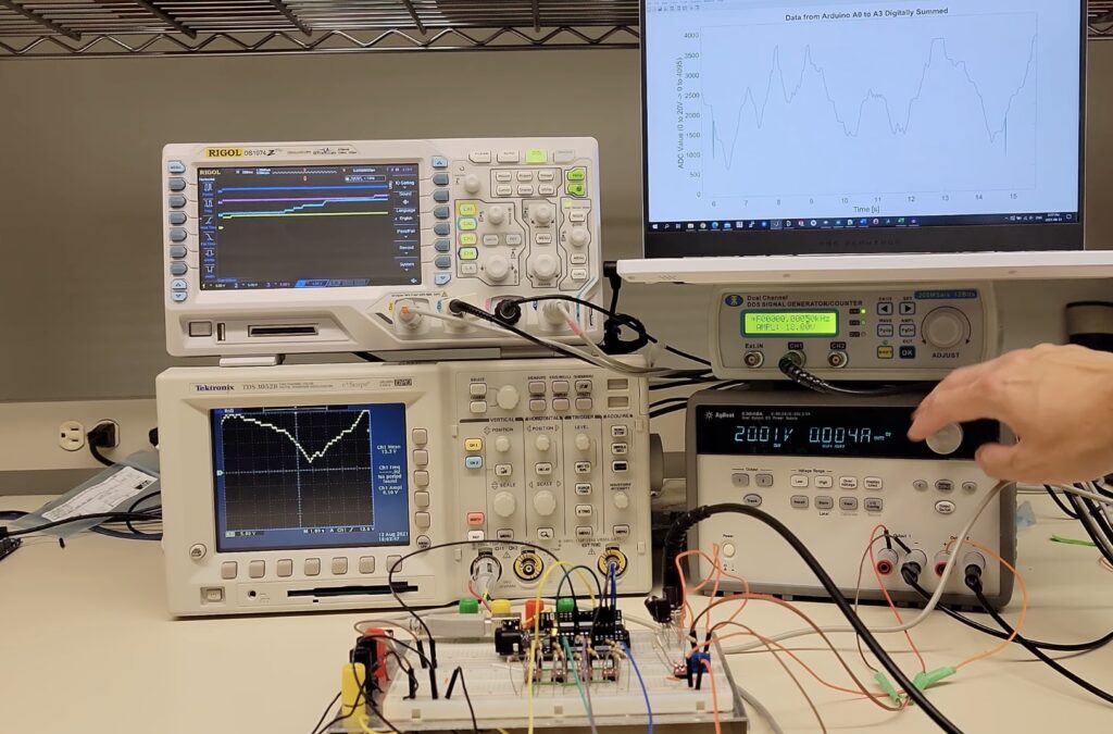
The Arduino Uno is well-known for its 10-bit 5V ADC within its ATmega328p, which means that it takes between 0 and 5V as input and produces a digital value that ranges from 0 to 1023. However, attempting to measure any voltage above 5V will cause some less-than-desirable results, such as creating magic smoke and destroying the IC. To get around this problem, some makers add a voltage divider that divides the incoming voltage by a predetermined factor. This solution reduces the resolution of the ADC, as a single unit of change in the digital value corresponds to a larger change in voltage. To address this, the YouTuber known as Techoyaki came up with a novel solution that can measure the full range of values without decreasing the resolution.
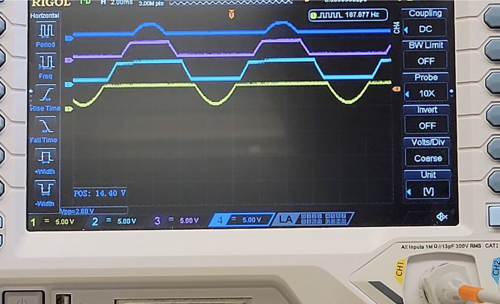
His project employs a series of four limiting rail-to-rail MOSFETs within a “quantizer” circuit to slice the incoming 20V current into discrete “chunks” that each range from zero to five volts. Just before the MOSFETs are four differential op-amps that essentially split the waveform into four layers. After the Arduino has read the values from the four analog input pins, it sums the values to produce the equivalent of a 12-bit ADC, thus leading to values that fall between 0 and 4095.

For more information about the circuitry and how this project was built, you can view Techoyaki’s video below!
Website: LINK


