With the 50th anniversary of the D-Day landings very much in the news this year, Adam Clark found himself interested in all things relating to that era. So it wasn’t long before he found himself on the Internet Archive listening to some of the amazing recordings of radio broadcasts from that time. In this month’s HackSpace magazine, Adam details how he built his WW2 radio-broadcast time machine using a Raspberry Pi Zero W, and provides you with the code to build your own.
As good as the recordings on the Internet Archive were, it felt as if something was missing by listening to them on a modern laptop, so I wanted something to play them back on that was more evocative of that time, and would perhaps capture the feeling of listening to them on a radio set.
I also wanted to make the collection portable and to make the interface for selecting and playing the tracks as easy as possible – this wasn’t going to be screen-based!
Another important consideration was to house the project in something that would not look out of place in the living room, and not to give away the fact that it was being powered by modern tech.
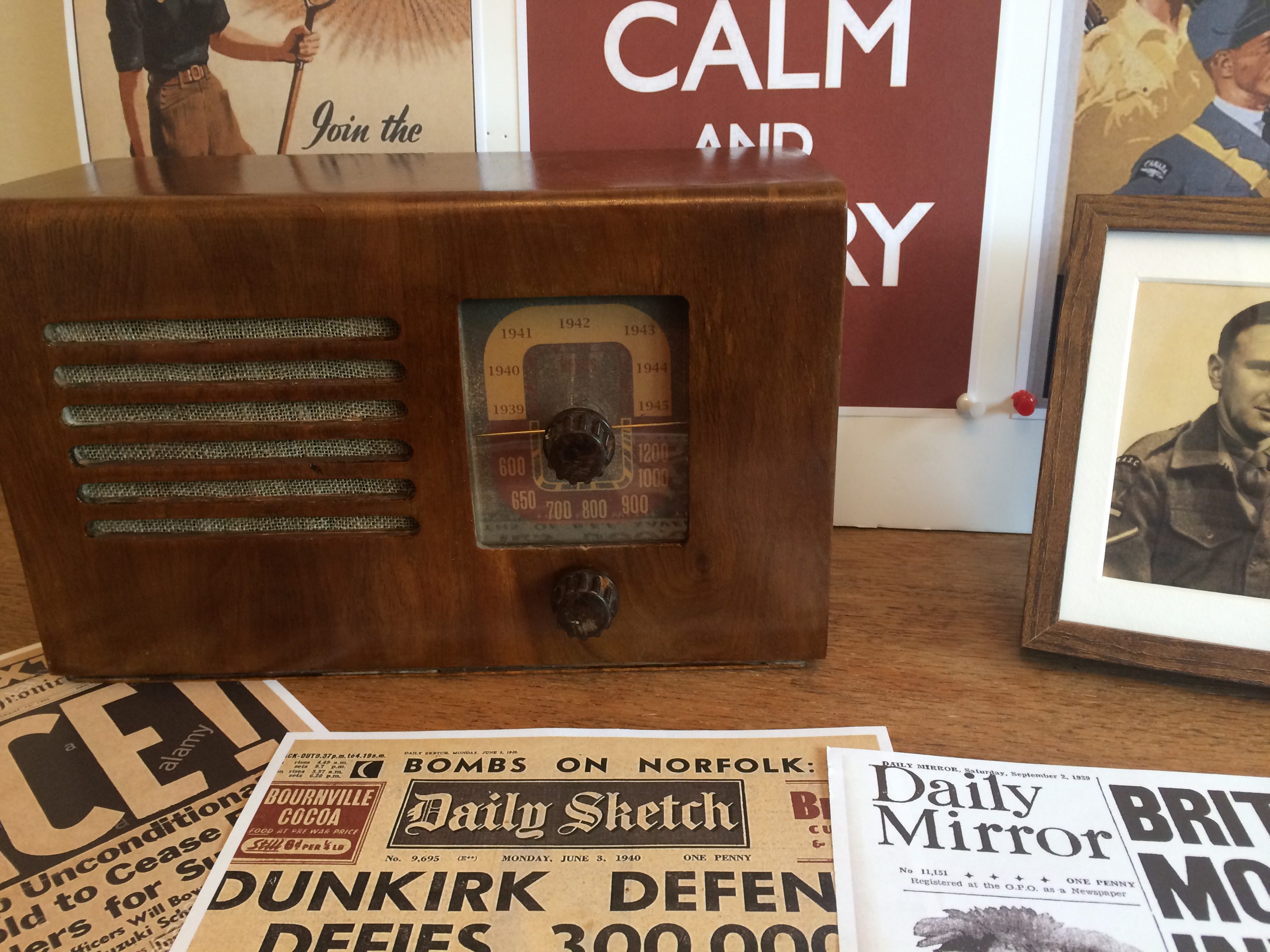
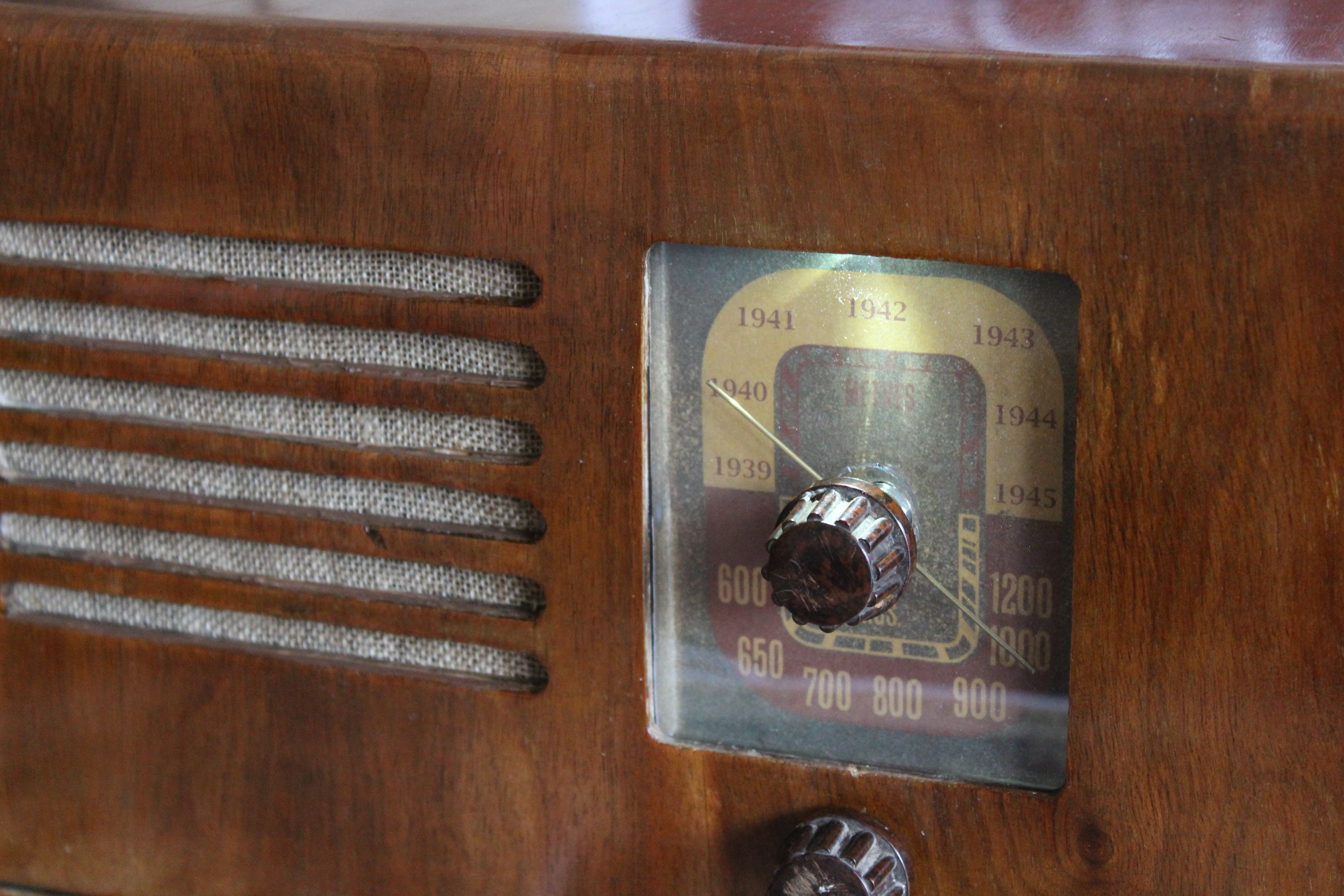
So I came up with the idea of using an original radio as the project case, and to use as many of the original knobs and dials as possible. I also had the idea to repurpose the frequency dial to select individual years of the war and to play broadcasts from whichever year was selected.
Of course, the Raspberry Pi was immediately the first option to run all this, and ideally, I wanted to use a Raspberry Pi Zero to keep the costs down and perhaps to allow expansion in the future outside of being a standalone playback device.
Right off the bat, I knew that I would have a couple of obstacles to overcome as the Raspberry Pi Zero doesn’t have an easy way to play audio out, and I also wanted to have analogue inputs for the controls. So the first thing was to get some audio playing to see if this was possible.
Audio playback
The first obstacle was to find a satisfactory way to playback audio. In the past, I have had some success using PWM pins, but this needs a low-pass filter as well as an amplifier, and the quality of audio was never as good as I’d hoped for.
The other alternative is to use one of the many HATs available, but these come at a price as they are normally aimed at more serious quality of audio. I wanted to keep the cost down, so these were excluded as an option. The other option was to use a mono I2S 3W amplifier breakout board – MAX98357A from Adafruit – which is extremely simple to use.
As the BBC didn’t start broadcasting stereo commercially until the late 1950s, this was also very apt for the radio (which only has one speaker).
Connecting up this board is very easy – it just requires three GPIO pins, power, and the speaker. For this, I just soldered some female jumper leads to the breakout board and connected them to the header pins of the Raspberry Pi Zero. There are detailed instructions on the Adafruit website for this which basically entails running their install script.
I’d now got a nice playback device that would easily play the MP3 files downloaded from archive.org and so the next task was to find a suitable second-hand radio set.
Preparing the case
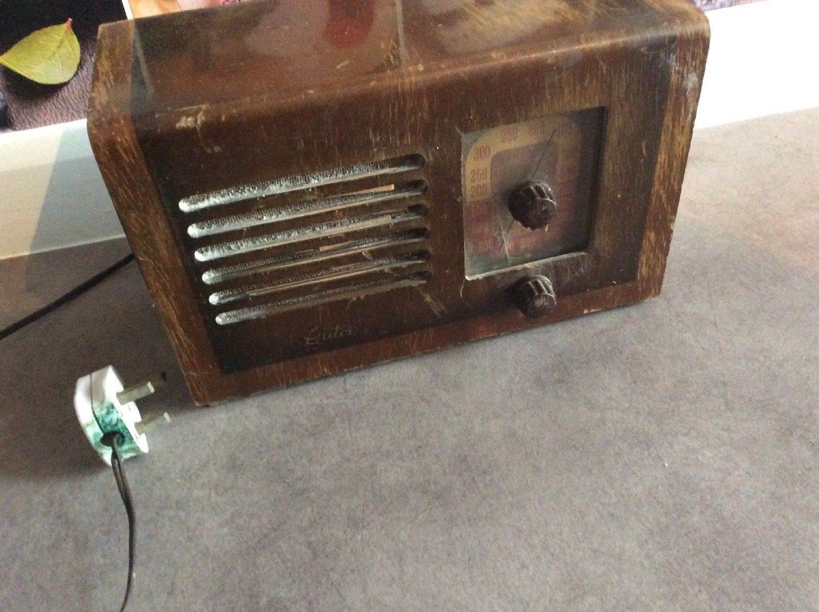
After a lot of searching on auction sites, I eventually found a radio that was going to be suitable: wasn’t too large, was constructed from wood, and looked old enough to convince the casual observer. I had to settle for something that actually came from the early 1950s, but it drew on design influences from earlier years and wasn’t too large as a lot of the real period ones tended to be (and it was only £15). This is a fun project, so a bit of leeway was fine by me in this respect.
When the radio arrived, my first thought as a tinkerer was perhaps I should get the valves running, but a quick piece of research turned up that I’d probably have to replace all the resistors and capacitors and all the old wiring and then hope that the valves still worked. Then discovering that the design used a live chassis running at 240 V soon convinced me that I should get back on track and replace everything.
With a few bolts and screws removed, I soon had an empty case.
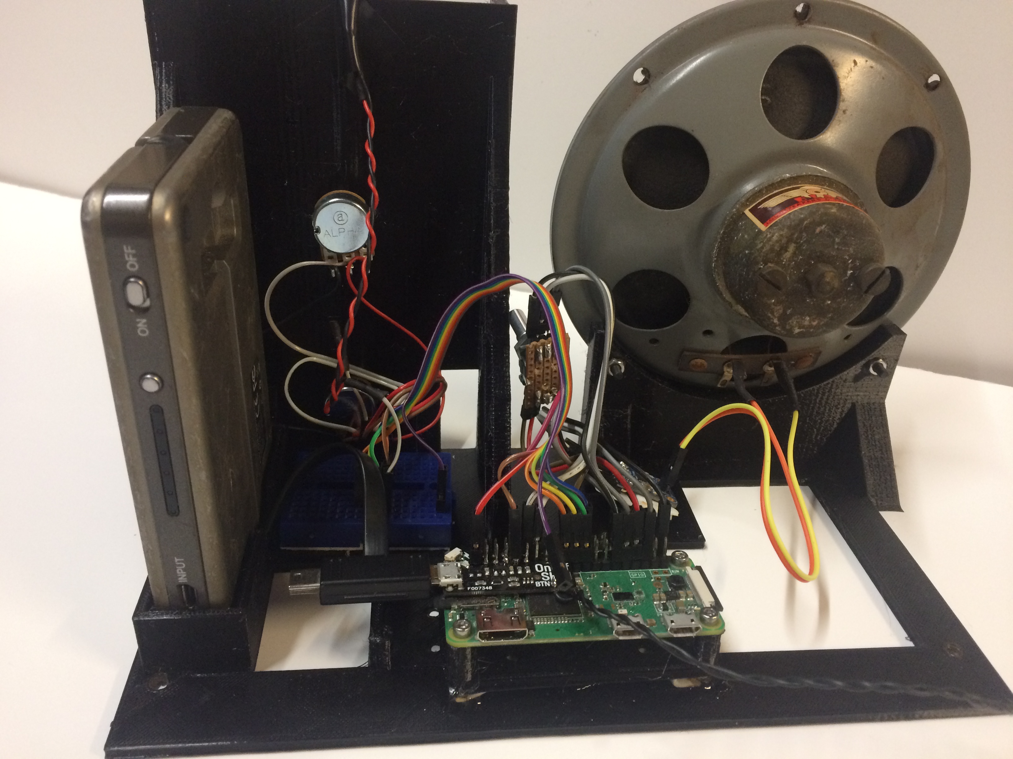
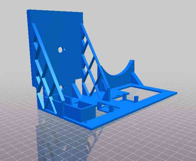
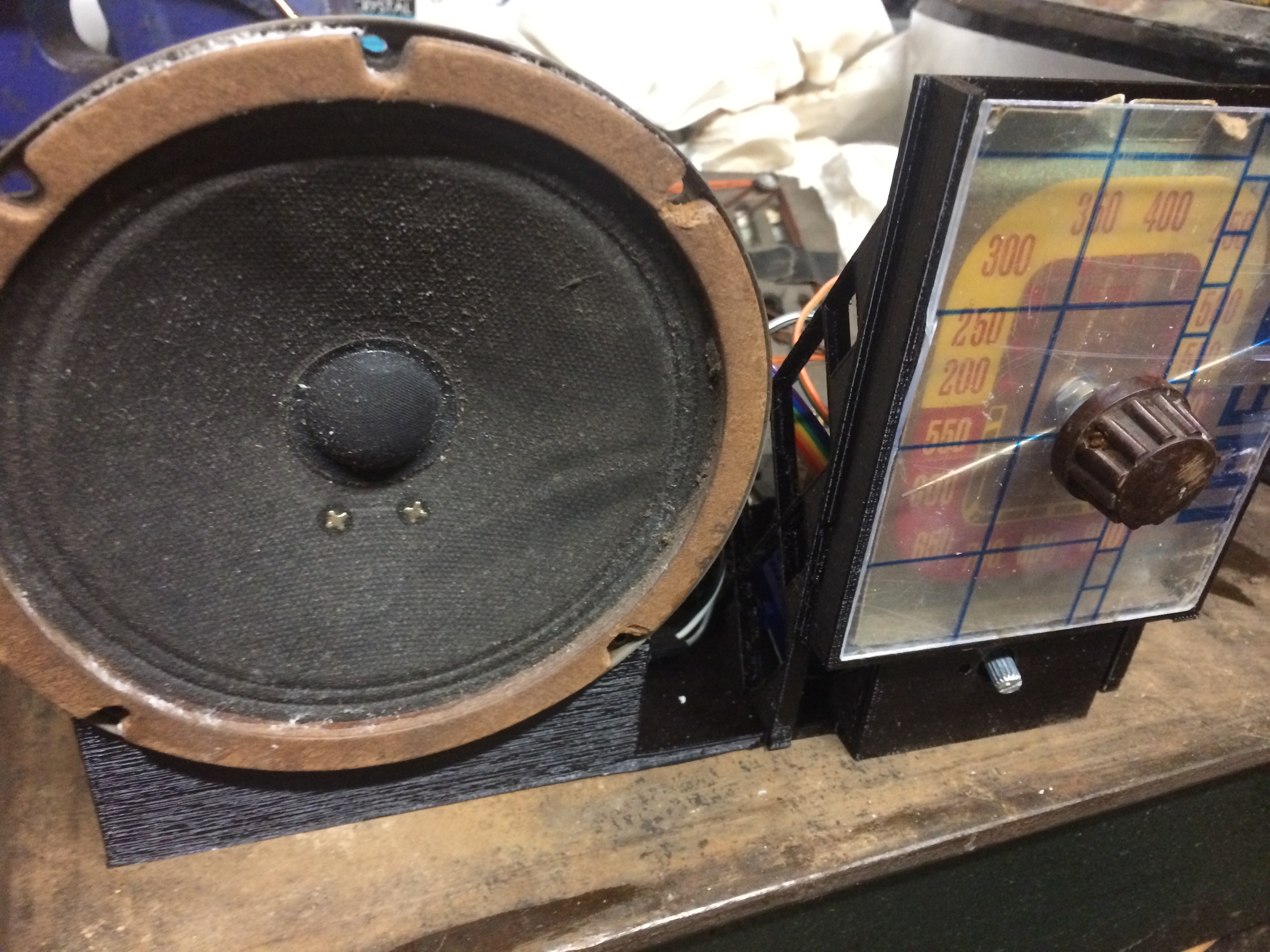
I then stripped out all the interior components and set about restoring the case and dial glass, seeing what I could use by way of the volume and power controls. Sadly, there didn’t seem to be any way to hook into the old controls, so I needed to design a new chassis to mount all the components, which I did in Tinkercad, an online 3D CAD package. The design was then downloaded and printed on my 3D printer.
It took a couple of iterations, and during this phase, I wondered if I could use the original speaker. It turned out to be absolutely great, and the audio took on a new quality and brought even more authenticity to the project.
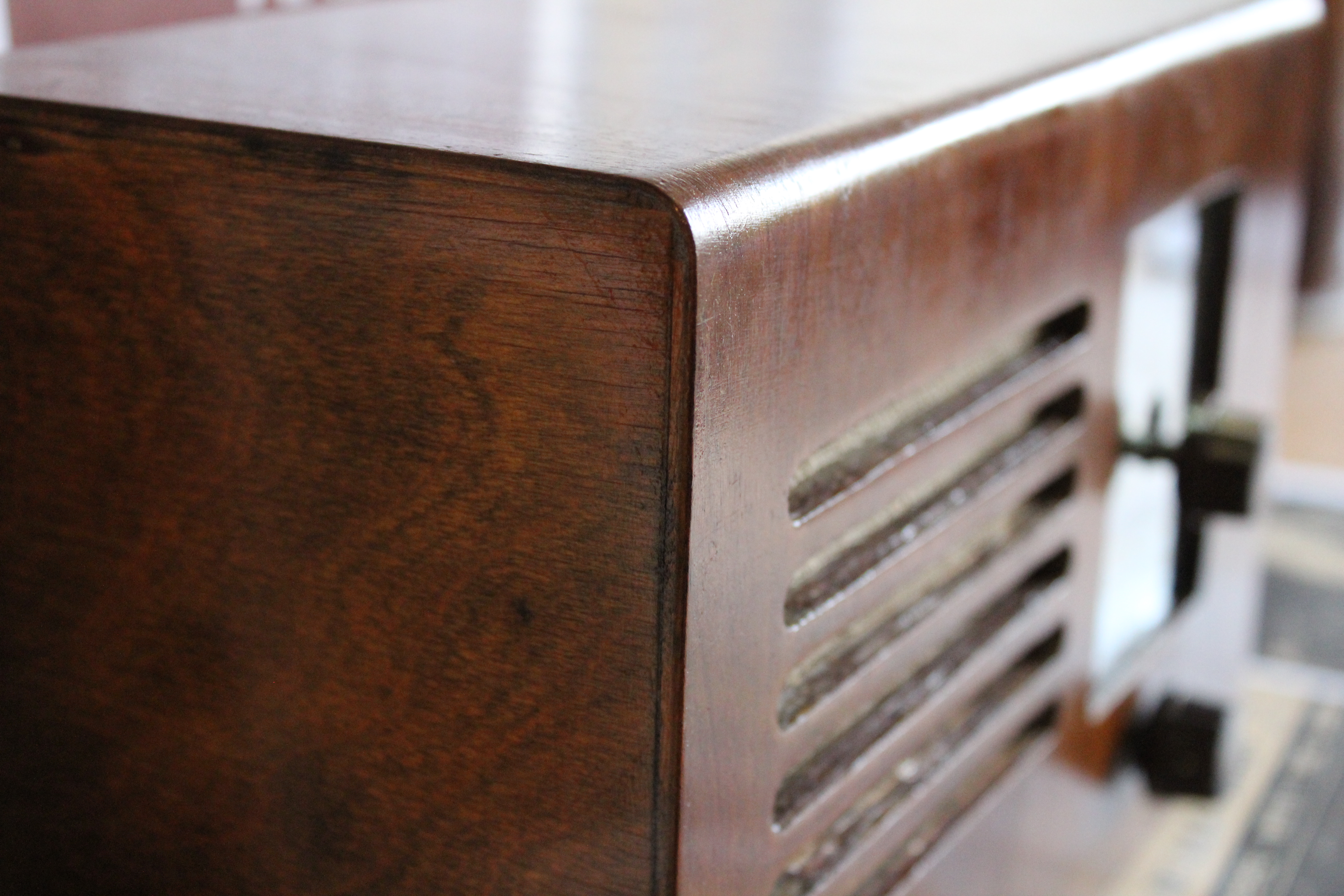
The case itself was pretty worn and faded, and the varnish had cracked, so I decided to strip it back. The surface was actually veneer, but you can still sand this. After a few applications of Nitromors to remove the varnish, it was sanded to remove the scratches and finished off with fine sanding.
The wood around the speaker grille was pretty cracked and had started to delaminate. I carefully removed the speaker grille cloth, and fixed these with a few dabs of wood glue, then used some Tamiya brown paint to colour the edges of the wood to blend it back in with the rest of the case. I was going to buy replacement cloth, but it’s fairly pricey – I had discovered a trick of soaking the cloth overnight in neat washing-up liquid and cold water, and it managed to lift the years of grime out and give it a new lease of life.
At this point, I should have just varnished or used Danish oil on the case, but bitten by the restoration bug I thought I would have a go at French polishing. This gave me a huge amount of respect for anyone that can do this properly. It’s messy, time-consuming, and a lot of work. I ended up having to do several coats, and with all the polishing involved, this was probably one of the most time-consuming tasks, plus I ended up with some pretty stained fingers as a result.
The rest of the case was pretty easy to clean, and the brass dial pointer polished up nice and shiny with some Silvo polish. The cloth was glued back in place, and the next step was to sort out the dial and glass.
Frequency, volume, glass, and knobs
Unfortunately, the original glass was cracked, so a replacement part was cut from some Makrolon sheet, also known as Lexan. I prefer this to acrylic as it’s much easier to cut and far less likely to crack when drilling it. It’s used as machine guards as well and can even be bent if necessary.
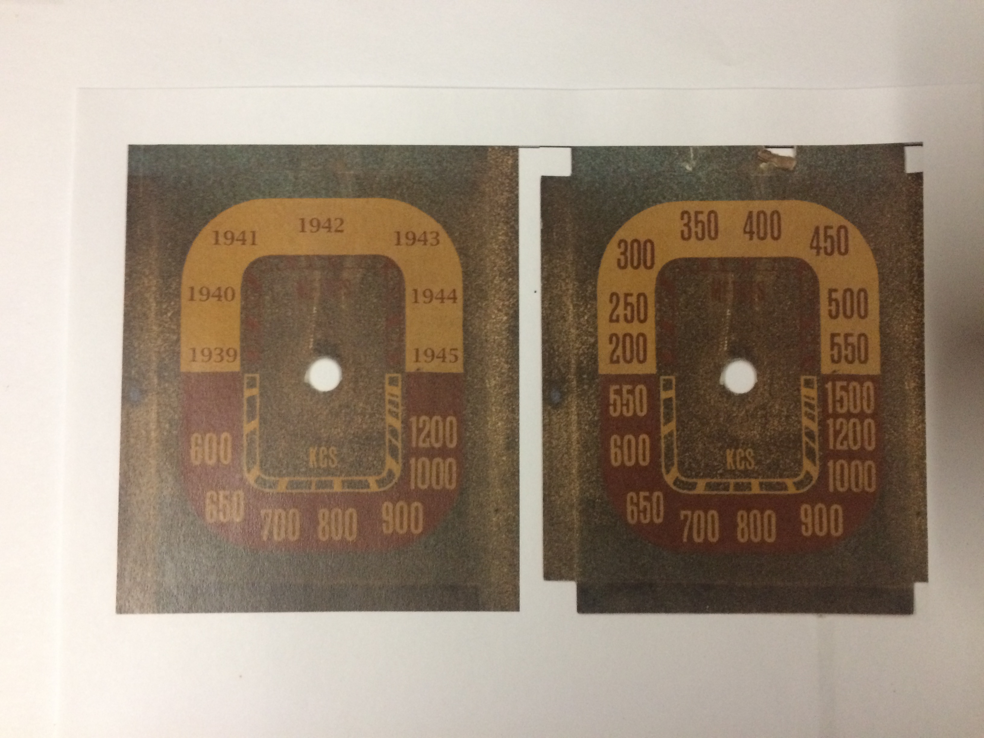
With the dial, I scanned it into the PC and then in PaintShop I replaced the existing frequency scale with a range of years running from 1939 to 1945, as the aim was for anyone using the radio to just dial the year they wanted to listen to. The program will then read the value of the potentiometer, and randomly select a file to play from that year.
It was also around about now that I had to come up with some means of having the volume control the sound and an interface for the frequency dial. Again there are always several options to consider, and I originally toyed with using a couple of rotary encoders and using one of these with the built-in push button as the power switch, but eventually decided to just use some potentiometers. Now I just had to come up with an easy way to read the analogue value of the pots and get that into the program.
There are quite a few good analogue-to-digital boards and HATs available, but with simplicity in mind, I chose to use an MCP3002 chip as it was only about £2. This is a two-channel analogue-to-digital converter (ADC) and outputs the data as a 10-bit value onto the SPI bus. This sounds easy when you say it, but it proved to be one of the trickier technical tasks as none of the code around for the four-channel MCP3008 seemed to work for the MCP3002, nor did many of the examples that were around for the MCP3002 – I think I went through about a dozen examples. At long last, I did find some code examples that worked, and with a bit of modification, I had a simple way of reading the values from the two potentiometers. You can download the original code by Stéphane Guerreau from GitHub. To use this on your Raspberry Pi, you’ll also need to run up raspi-config and switch on the SPI interface. Then it is simply a case of hooking up the MCP3002 and connecting the pots between the 3v3 line and ground and reading the voltage level from the wiper of the pots. When coding this, I just opted for some simple if-then statements in cap-Python to determine where the dial was pointing, and just tweaked the values in the code until I got each year to be picked out.
Power supply and control
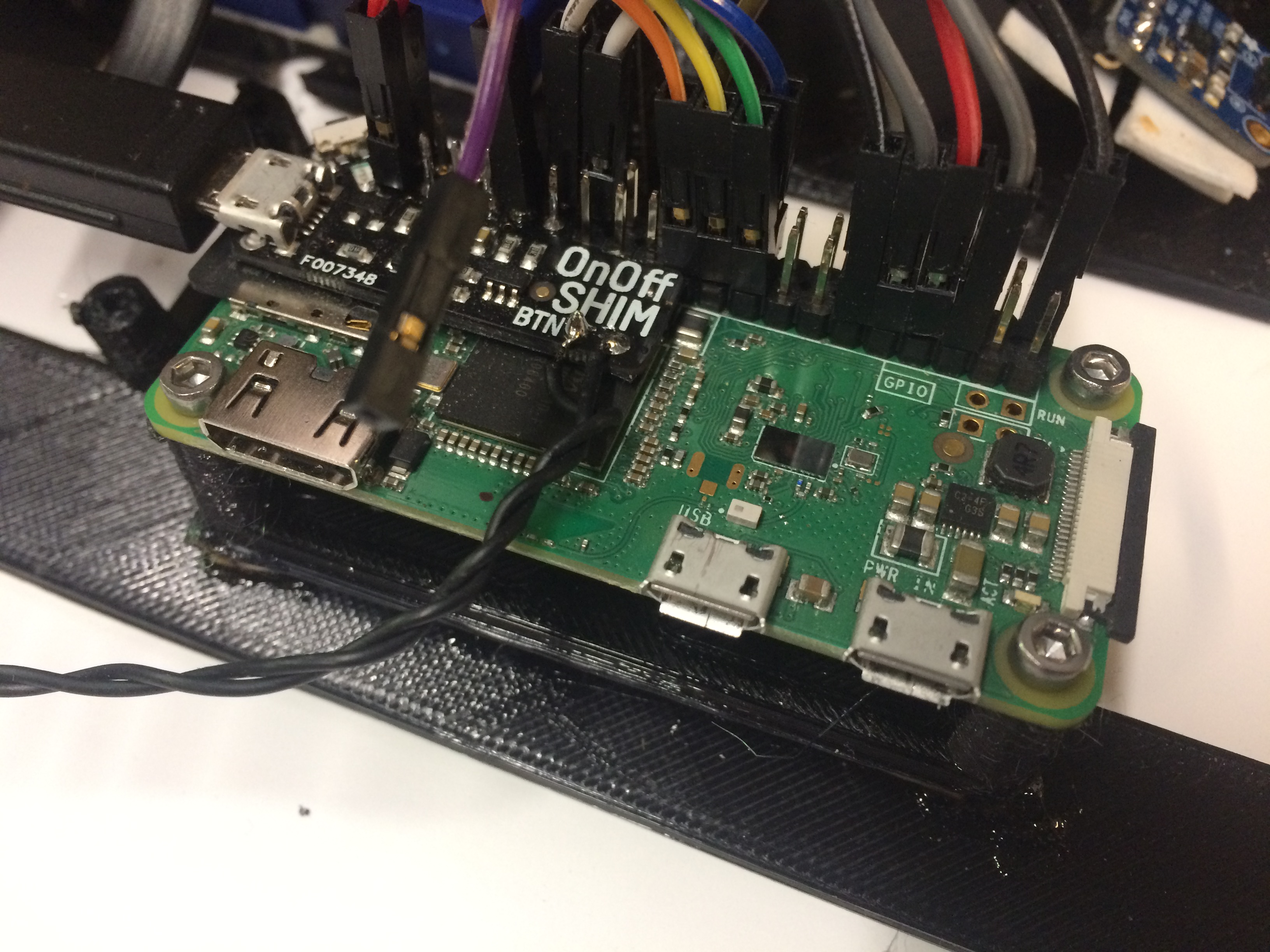
One of the challenges when using a Raspberry Pi in headless mode is that it likes to be shut down in an orderly fashion rather than just having the power cut. There are lots of examples that show how you can hook up a push button to a GPIO pin and initiate a shutdown script, but to get the Raspberry Pi to power back up you need to physically reset the power. To overcome this piece of the puzzle, I use a Pimoroni OnOff SHIM which cleverly lets you press a button to start up, and then press and hold it for a second to start a shutdown. It’s costly in comparison to the price of a Raspberry Pi Zero, but I’ve not found a more convenient option. The power itself is supplied by using an old power bank that I had which is ample enough to power the radio long enough to be shown off, and can be powered by USB connector if longer-term use is required.
To illuminate the dial, I connected a small LED in series with a 270R resistor to the 3v3 rail so that it would come on as soon as the Raspberry Pi received power, and this lets you easily see when it’s on without waiting for the Raspberry Pi to start up.
The code
If you’re interested in the code Adam used to build his time machine, especially if you’re considering making your own, you’ll find it all in this month’s HackSpace magazine. Download the latest issue for free here, subscribe for more issues here, or visit your local newsagent or the Raspberry Pi Store, Cambridge to pick up the magazine in physical, real-life, in-your-hands print.
Website: LINK

Schreibe einen Kommentar
Du musst angemeldet sein, um einen Kommentar abzugeben.