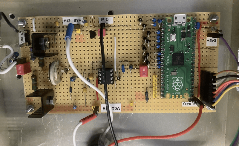
Wolfgang had made a hardware-based arbitrary waveform generator before, but having researched the capabilities of the RP2040 microcontroller and its support for DMA and PIO, he realised Raspberry Pi Pico would be ideal for amplifying waveform signals. MicroPython, which Pico natively supports, also happens to be Wolfgang’s preferred programming language. He decided to add an output stage “to amplify the signal of the RP2040 and make it short circuit-proof,” plus a display to make the results clearer. The amplifier was needed because the RP2040 can only drive small loads, he explains. Initial tests using a breadboard proved the concept worked well, while online research suggested other users were also searching for a device of this kind, and may well appreciate having a design they could use too.
In praise of Pico
“Pico is the perfect microcontroller board for this project. It has plenty of RAM and flash memory. The RP2040’s CPU clock is specified for 125MHz, but runs reliably at 250MHz, which for my project enables output frequencies well above 20MHz, while the SPI interface can drive a TFT display for the user interface,” Wolfgang says of the Pico’s impressive specifications.
It wasn’t all plain sailing, though. “Ideally a function generator should have a clean output signal with no distortions or noise.” However, using Pico to both generate the wave and power the TFT display via the SPI interface resulted in a noisy output signal because of cross-talk from the SPI interface to the PIO output pins, Wolfgang reports. Making some changes to his breadboard layout improved things, but didn’t get rid of all the signal noise. Instead, he took charge of how the TFT updated. “Once the user has entered or adjusted the wave and started the generator output, the display refresh is turned off. This turns off the SPI, which reduces most of the noise,” he explains.
Community input
A fan of rapid prototyping, he split the development into three phases beginning with the generator engine. Here, he added some control code that fellow maker Rcgo had written up as an Instructable that enabled Raspberry Pi Pico to calculate a wave and program the DMAs and PIO. Wolfgang was able to modify this for the AWG core, adding a list of data elements the generator module would use to create the desired wave based on the user’s input. Another community-contributed project, Peter Hinch’s micro-gui, proved “the perfect base to build a user interface for small embedded systems.” Peter helped Wolfgang put together a knob widget to go with the two push-buttons and rotary encoder he’d set up to work alongside micro-gui and the TFT controls. These dials were critical, since they govern changes to the waveform created.
The class AB output stage consists of discrete components including “a nice video driver IC that provides low output impedance,” while compromising with an 8-bit DAC (rather than a better resolution 10-bit one) avoided timing problems at higher frequencies. “Four wave data samples are loaded every other clock cycle, so there is time for the DMAs to reconfigure, while the PIO still has data to shift out. Running the CPU at 250MHz, waves can be generated well above 20MHz,” Wolfgang reports. Just a few days after he started designing it, the so-called poor man’s AWG was used to diagnose and fix his friend’s tube amplifier. “One more happy friend,” says Wolfgang.


