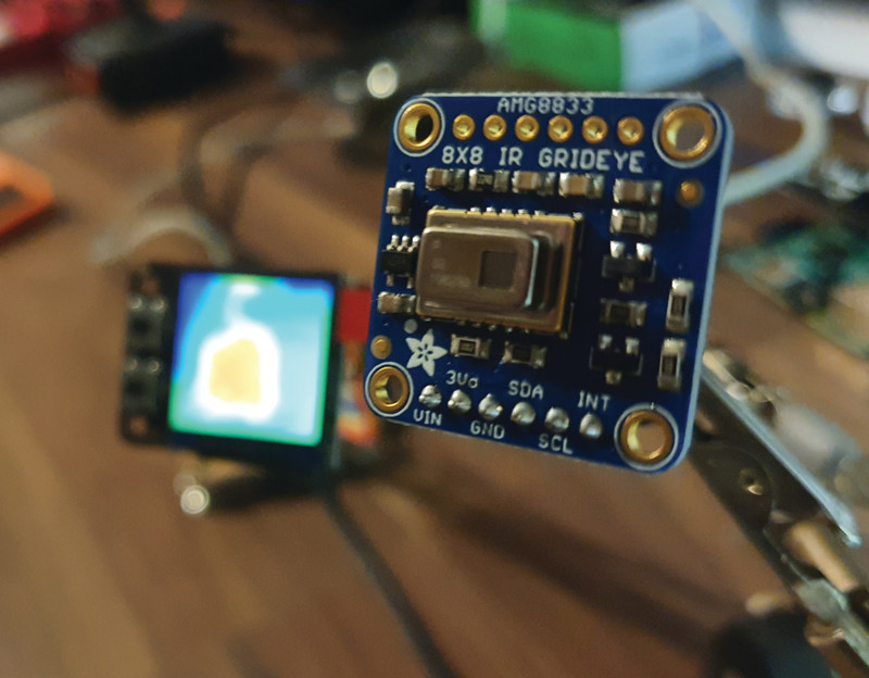
When the gauntlet was first laid down, Martin decided it would be a good time to use an Adafruit thermal sensor he’d already bought. “Our libraries already use commercial thermal visitor counters, so I thought I’d build my own,” he reasoned. Years of designing projects has taught him that it’s best not to get too hung up sticking with your original plans. Instead, he says, it’s best “to get started and see where the project takes you!” He advises: “it’s always good to do lots of research up front and have a clear idea of what you want to achieve, but some of the most rewarding projects are those where you make at least some of it up as you go along.”
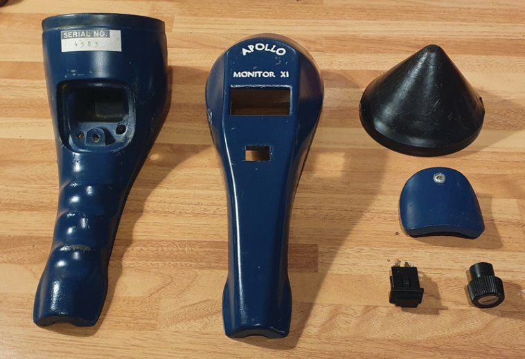
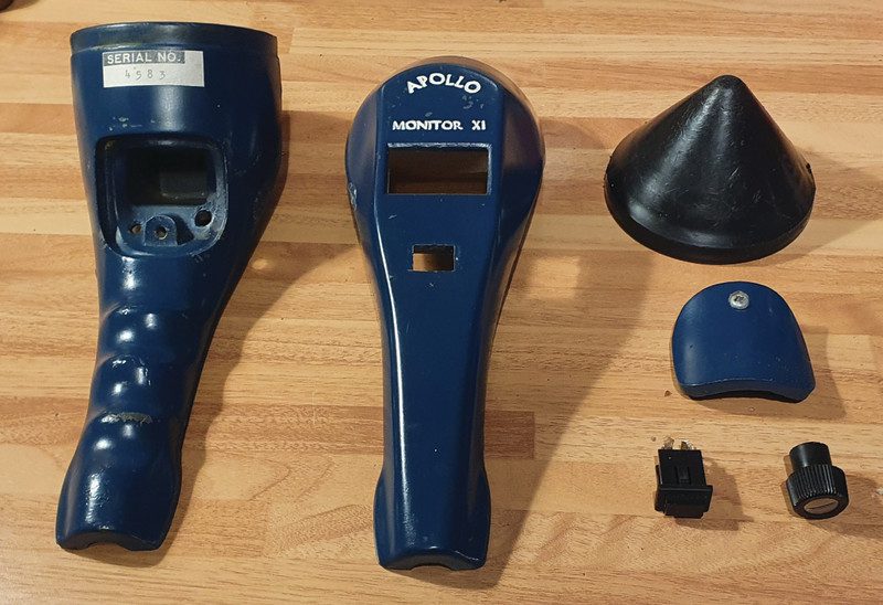
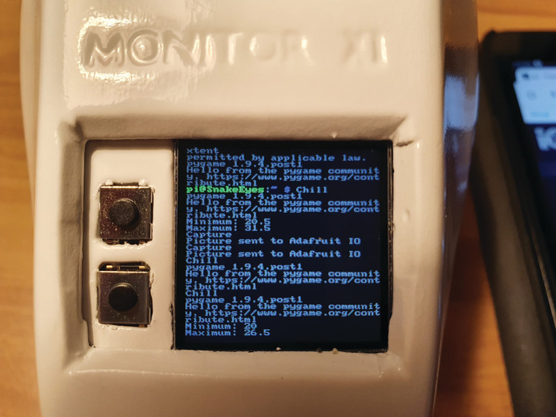
Martin expected it to be a quick build. “I thought I’d pop the components into an old infrared flash gun in an afternoon,” he recalls. Unfortunately, the case was too small, so he had to rethink. Digging around in his dusty boxes of old tech for an alternative, the Apollo monitor caught Martin’s eye. “It really leapt out at me as it was just the right size, and also a perfect ‘hold and point’ shape. It was easy to imagine it as a thermal camera.”
Change of plan
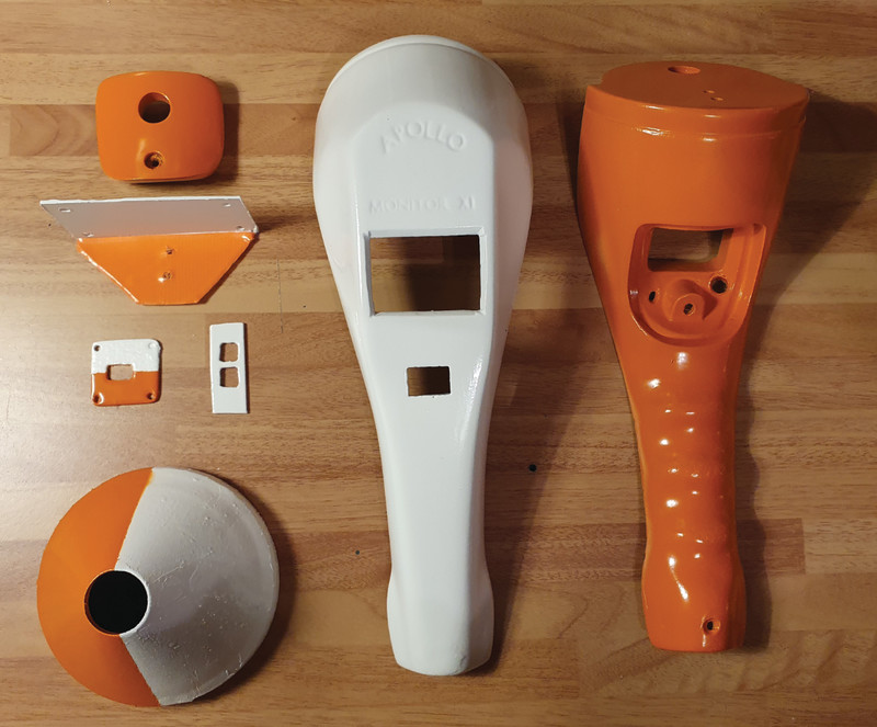
Parts for the project were sourced online, costing around £70 in all. The biggest expense was the thermal sensor. After connecting the screen, sensor, and Raspberry Pi Zero W, Martin started working out what extra switches he’d need, plus how to power the device. He was able to make use of small bits of leftover plastic as circuit board covers, and spent a long time trimming the original case to make the new components fit.
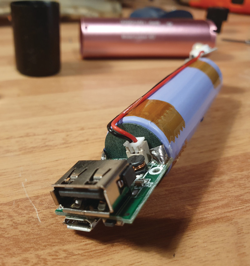
The screen and sensor are connected to the GPIO pins via jumper cables. To prevent them disconnecting while cramming everything into the grip, Martin hot-glued them in place. With a USB battery pack fitted, he was ready to start testing.
Altering the script
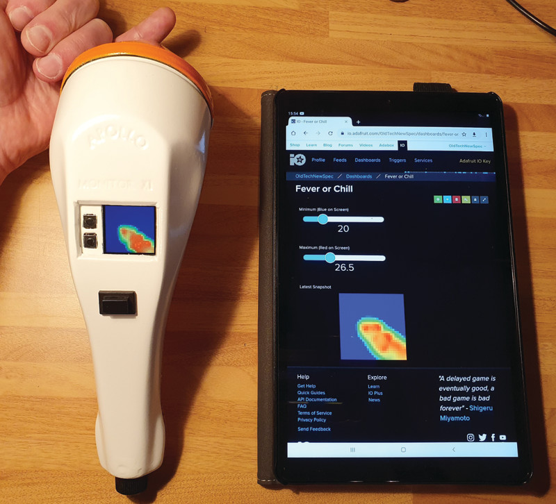
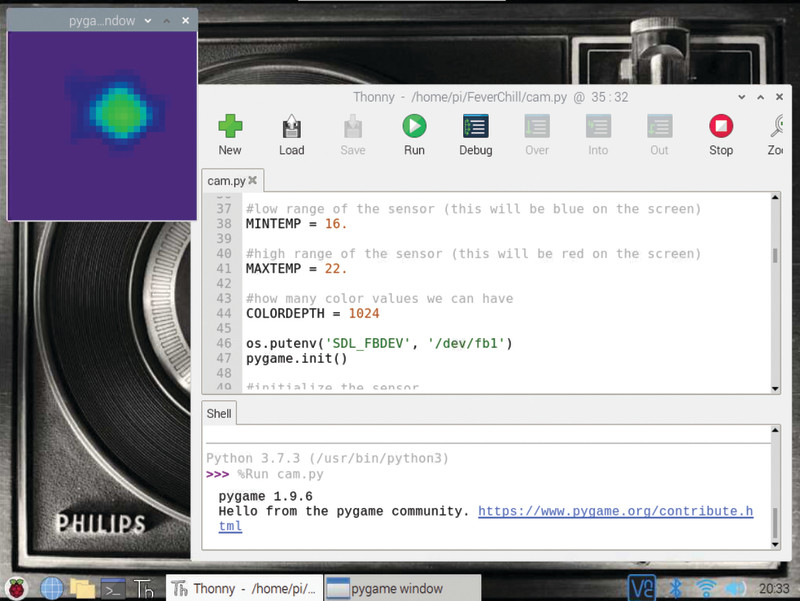
Software for the project is based on Adafruit’s Python code for the thermal sensor. “All I’ve done is added in some extra code to handle more button presses, and some additional integrations with Adafruit.io, to enable uploading the captured images and using dashboard sliders to set the temperature threshold,” explains Martin, modestly.
Apollo Pi took him a month to build, devoting an hour each evening to the project. “I enjoyed taking my time with it and not rushing to finish,” he says. As he doesn’t have a 3D printer, he had to make everything himself. “A 3D printer would make a much neater job of such tiny parts, but it was incredibly satisfying whittling and filing them by hand!”
Sensor info and code can be found at Apollo Pi.

