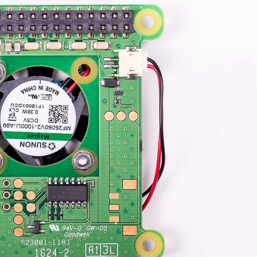
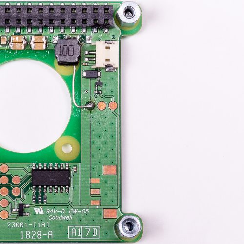
One of the neat new features of the Raspberry Pi 3 Model B+ is its support for IEEE 802.3af Power-over-Ethernet (PoE). This standard allows up to 13W of power to be delivered over the twisted pairs in an Ethernet cable without interfering with the transmission of data. The Raspberry Pi board itself provides a PoE-capable Ethernet jack and circuit protection components; the power regulation electronics, which would be too costly and bulky to include on the main board, live on a separate HAT.
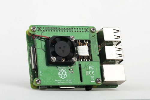
The Raspberry Pi 3B+ wearing a PoE HAT
When we announced the 3B+, we revealed that an official Raspberry Pi PoE HAT was in the works and, after a few unforeseen production delays, we we released this HAT at the end of August. Feedback was, and remains, generally very positive; but fairly quickly, we started to see some reports from users who were experiencing issues.
The problem
The problem they reported was this: when powering certain Raspberry Pi units via the PoE HAT, it was not possible to draw the full rated current from the USB ports.
Our 5V USB output, denoted VBUS, is fed by the main 5V rail via a current-limiting switch. This switch is designed to protect the system by detecting short-circuit, over-current, or reverse-voltage events, and disconnecting the USB ports in response. Our current-limiting switch is set to a limit of just over 1A.
Despite the PoE HAT’s ability to supply up to 2.5A, the experiments we ran in response to the reports suggested that, when it was used to supply some boards, the USB supply would trip out at a much lower current. Mice and keyboards worked fine, but higher-current devices such as wireless dongles and hard disks would fail.
Our initial theory was that the PoE HAT was injecting noise into the Pi via the 5V rail, and that this was somehow upsetting the switch. However, we were able to rule this out, since we found no evidence of high-frequency noise at the input to the switch. Another theory was that the flyback transformer’s close physical proximity to the switch was somehow coupling noise in. But we were able to rule this out as well: we showed that the behaviour persisted when the HAT was connected using a right-angle header, which moves the power electronics away from the Raspberry Pi.
What was happening?
The PoE HAT works by converting the incoming 48V from the Ethernet lines to 5V using a flyback transformer. In simple terms, the primary side of the transformer is switched across the 48V, and energy is stored in the transformer in the form of a magnetic field. The primary is then disconnected and the magnetic field collapses. This changing magnetic field induces a voltage (scaled based on the transformer turns ratio) in the secondary, which is rectified by a schottky diode and output capacitance. This output capacitance is formed from the output capacitors on the PoE HAT itself, the capacitors on the Raspberry Pi 5V rail, and, when the switch is on, the VBUS reservoir capacitors.
The switching frequency of the flyback transformer is relatively low (~100 kHz). This means that when the system is under load, each switching cycle must transfer a relatively large amount of energy. During each cycle, the 5V rail is discharged according to the load on the system, and charged up again by the flyback’s secondary, dumping more energy into the caps. In each cycle, a spike of high current is pushed through the output diode into the capacitors.
To cut a long story short, putting a current probe on the input to switch showed large current spikes, as energy from the flyback made its way into the VBUS reservoir capacitors. This was expected. However, it turned out that the switch was erroneously registering these spikes as true over-current events. The switch is supposed to have a filter that allows it to ignore brief spikes, but we discovered that only one of the two approved versions of the switch did this correctly.
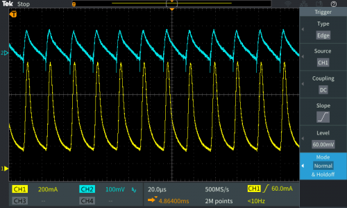
Current into switch (yellow) and VBUS voltage (blue)
If it’s not been tested, it’s broken
It’s a truism that if you don’t test an aspect of a design, it will certainly be broken. Those of us with a Broadcom background sometimes refer to this as Alan Morgan’s rule, after its most enthusiastic proponent.
Extensive testing over all configurations, operating parameters, and use cases is the only way to minimise the likelihood of releasing a product with a hardware issue. Even relatively simple hardware can end up catching you out by throwing up some unexpected bug or issue. And even the big guys with huge development teams and test labs occasionally mess things up — anyone remember the Pentium FDIV bug?
We made several mistakes with the first version of the PoE HAT:
- USB load testing was performed using boards that had the working switch
- Our field testing programme was abbreviated because the product was late
- We didn’t inquire as to whether our field testers were using high-current peripherals (they weren’t)
It’s embarrassing to have released a product with a bug like this, but it’s a lesson well-learned, and we will be improving our internal processes to prevent a recurrence.
The solution
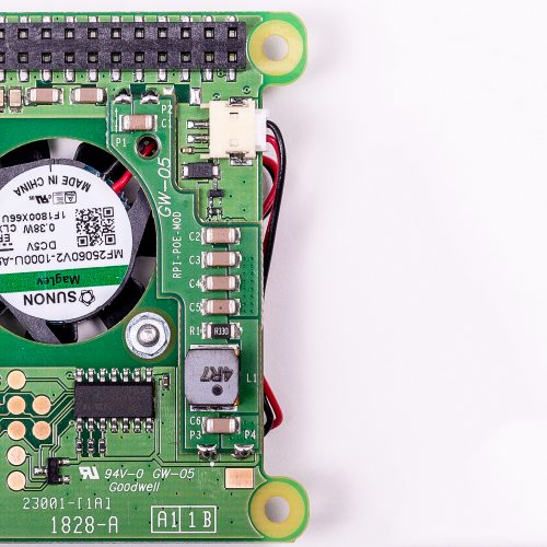
Fortunately, this bug turned out to be easy to fix. We designed an L-C filter to apply further smoothing to the output current from the HAT. The filter consists of a little extra input and output capacitance and a 4.7µH inductor (chosen to have a suitable current rating and DC resistance), as well as 330mR resistor in parallel to provide damping. We were even able to wrap the mod up in a little mezzanine PCB that fits neatly underneath the board.
Once we had confirmed that there was a problem with the PoE HAT, we took the product off sale, and recalled and reworked the outstanding units. We are now happy to announce that most Approved Resellers should now have the revised boards in stock. We believe that most people who have been affected by this issue have already returned their PoE HATs for a refund; if you’re experiencing issues and haven’t yet returned your product, you can get in touch with your reseller to arrange a replacement.
I’d like to thank the members of the Raspberry Pi engineering team, our contract manufacturing partners Taijie, our licensee partners and Approved Resellers, and also the community members who kindly tested prototypes of the fixed board design. This hasn’t been the easiest product launch in our history, but hopefully the lessons learned have set us up well for the future.
Website: LINK

